Friday 6 September 2019

Tim's Racer (Arduino)


A Little Race game for the Arduino

on a Nokia LCD Screen via I2C Module.


I have created a HEX file of this game Tims_Racer.zip
Inside the zip the are versions for the UNO and NANO, with or without the bootloader (old bootloader for Nano)
Also there is a copy of XLoader to upload the HEX to the Arduino.

It needs the same setup as Brick a Bottle or Three.
The pins for the buttons on the Arduino are as follows.

A0 = Button 1
A1 = Button 2
A2 = Button 3
A3 = Button 4
D8 = Button LED
D9 = Piezo

Remember the Arduino is has 5 volt data and the Nokia Screen is 3.3 volt.
Power going to the PCF8574 should only be 3.3 volt.
I have since added 10k resistors in line to the data leads connected to the Nokia screen.
Use at your own risk.

Wednesday 7 August 2019

Brick a Bottle or Three (Arduino)


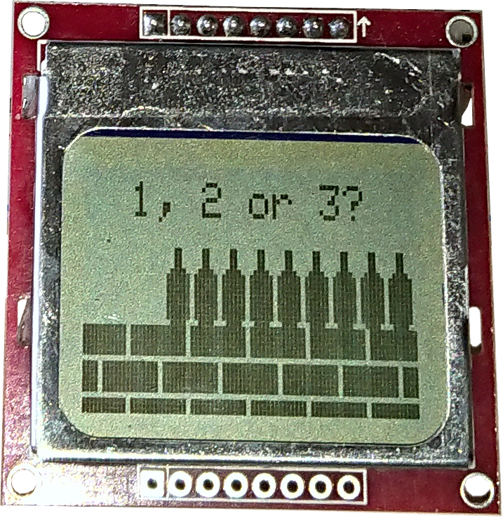
A little game to show how to use a PCF8574 with a Nokia 5110 screen.

Components:

Arduino

Breadboard (and leads)

Nokia 5110 Screen


PCF8574
I2C Serial Interface Board Module for 1602LCD Display (PCF8574)
PCF8574 Module


Piezo (for sound)
A bit of corrugated card board to amplify the sound made by the piezo.


4 x Push on Buttons

Battery


Data for PCF8574 (Remote 8-bit I/O expander for I2C-bus with interrupt)
Data for PCD8544 (48 × 84 pixels matrix LCD controller/driver)

In this project I am using the module designed for 0216 LCD diplay.

There are several reasons for using this module.
The first time I bought a Nokia 5110 screed the advert say it was 5v compatible (I fried it), no it isn't, it's 3.3 volt.
This can be sorted using resistors as voltage dividers, or MOSFET circuits.
The Nokia 5110 screen also communicates via SPI requiring 4 communication lines and power.
If we use the Module:
The PCF8574 requires only 2 communication lines and power.
Also the module has a transistor connected to PFC8574 GPIO pin 3, which connects Header Pin 16 to GND. (Used for switching the LED).
If the module is powered by 3.3 volt, it will communicate with 3.3 volt to the Nokia 5110 screen and still be able handle the I2C communication from the Arduino.

The circuit of the Module:


Connections:


I2C Serial Interface Board Module for 1602LCD Display
Module 4 pin header
Arduino
GND
GND
VCC
3.3v
SDA
A4
SCL
A5


Module 16 pin header
Nokia Screen
Pin 01
Pin 8 Nokia 5110 Screen
Pin 02
Pin 6 Nokia 5110 Screen
Pin 03
NC
Pin 04
NC (free GPIO_0)
Pin 05
NC (free GPIO_1)
Pin 06
Pin 1 Nokia 5110 Screen
Pin 07
NC
Pin 08
NC
Pin 09
NC
Pin 10
NC
Pin 11
Pin 2 Nokia 5110 Screen
Pin 12
Pin 3 Nokia 5110 Screen
Pin 13
Pin 4 Nokia 5110 Screen
Pin 14
Pin 5 Nokia 5110 Screen
Pin 15
NC
Pin 16
Pin 7 Nokia 5110 Screen

Buttons
Header Pin
Arduino
1 (Button 1)
A0
2 (Button 2)
A1
3 (Button 3)
A2
4 (Button 4)
D7
5 (common pin)
GND

Piezo Sounder
Connection
Arduino
Does not matter
GND
D11


The code:

Tims_Brick_a_Bottle_or_Three.

Credit for the library <PCF8574_PCD8544.h> used in the code goes to: Maxint R&D
The library is used like most display libraries.
It is defined like: PCF8574_PCD8544 display = PCF8574_PCD8544(0x27, 7, 6, 5, 4, 2);
It also uses <Adafruit_GFX.h> library (credit to: Limor Fried/Ladyada) so the commands to draw graphics, is as the Adafruit GFX library.

In setup:

 I have made pins A0, A1 and A2 raise an interrupt when button 1, 2 or 3 is pressed.

PCICR = 0b00000010; // Pin Change Interrupt Enable.
PCMSK1 = 0b00000111; // Enable Pin Change Interrupt for A0, A1, A2.
sei(); //enable interrupts.

I have enabled pullup resistors on the button pins. The buttons close to GND.
(the button module has capacitors to help with bounce)

pinMode(BUTTON_1, INPUT_PULLUP);
pinMode(BUTTON_2, INPUT_PULLUP);
pinMode(BUTTON_3, INPUT_PULLUP);
pinMode(LED_ON, INPUT_PULLUP);

The function to receive the interrupts is ISR(PCINT1_vect){  //code goes here  }

The images to draw the bottles are made from char Array.

Example:
//bottle 6x16
static const unsigned char PROGMEM bottle_img[] =
{ B00110000,
B00110000,
B00110000,
B00110000,
B01111000,
B11111100,
B11111100,
B11111100,
B11111100,
B11111100,
B11111100,
B11111100,
B11111100,
B11111100,
B01111000
};

Although the bottle is only 6 bits wide, the library only works with 8 bit values.
But when using the library command to draw the image, we still the value 6 for the width.
display.drawBitmap(positionX, positionX, bottle_img, 6, 15, 1);

The sound is produced using the tone function.
Gluing the piezo to the back of a piece of card amplifies the sound.


Friday 2 August 2019

Tim's Quiz Master


Identifies first Player Button pressed out of five buttons.
Based on a capacitor and MOSFET configuration.
Depending on LED colour (LED resister used), it holds off other buttons for 30 to 60 seconds. (hold time can be increased by increasing the value of the capacitors)
It has a Reset Button to reset all the Player Buttons.

It needs 5 volt power (no greater).
Socket is for a 5.5mm barrel jack.

Can use something like this:
or


Need Cables to connect the Buttons to the Master Controller.
(Small screwdriver)